Case studies
Four wedges, described honestly.
Chipira is pre-launch. What follows are the four wedge workflows we are designing our design-partner programme around — the problem, the approach, the metric and the baseline. When they carry real results, this page will say so.
A note on evidence
What this page is, and is not
Most early-stage companies fill this page with composite “case studies” that no customer would recognise. We would rather be useful.
Each workflow below sets out the failure mode, how Chipira attacks it, the metric we would agree to be judged on, and how the baseline is established. The numbers are modelled design targets, marked as such. None of them is a customer result, because we do not yet have customer results to report.
If you are evaluating vendors in this category, we would suggest asking every one of them which numbers on their case-study page are measured, on whose line, and against which baseline. The answers are informative.
Wedge 01
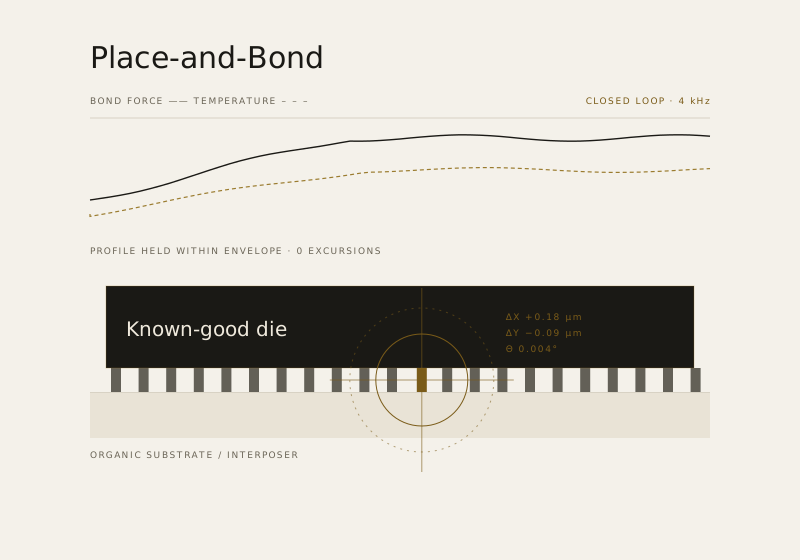
Hybrid-bonding alignment drift
The failure mode
A fraction of a micron, and the module is gone
Hybrid bonding joins surfaces copper pad to copper pad at sub-micron alignment with no tolerance for particles. Placement and rotation drift with thermal state, stage wear and material lot, and the excursion is often only visible after a batch has already been bonded. Approach: continuous alignment metrology feeding a closed-loop correction inside a tight action envelope, with particle flagging escalated to handling before a bond is attempted. Metric: alignment excursions per thousand bonds and bond yield, against a shadow-mode baseline. Status: design-partner programme [ASPIRATIONAL].
Wedge 02
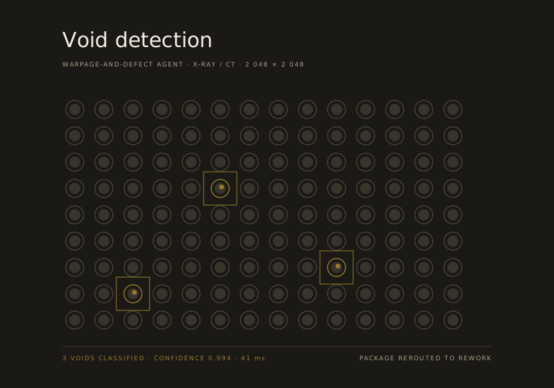
X-ray and CT void detection
The failure mode
The defect that is only visible after the value is spent
Voids under bumps and in the bond line are invisible to the bonding step that produced them and expensive by the time X-ray or CT reveals them. Fixed thresholds either escape real defects or condemn good packages. Approach: fine-tuned volumetric detection at line rate with confidence and evidence attached, feeding automatic rework, re-inspection or scrap disposition before further value is added. Metric: classification accuracy and escape rate against the engineer plus existing inspection baseline; scrap avoided per thousand packages. Status: design-partner programme [ASPIRATIONAL].
Wedge 03
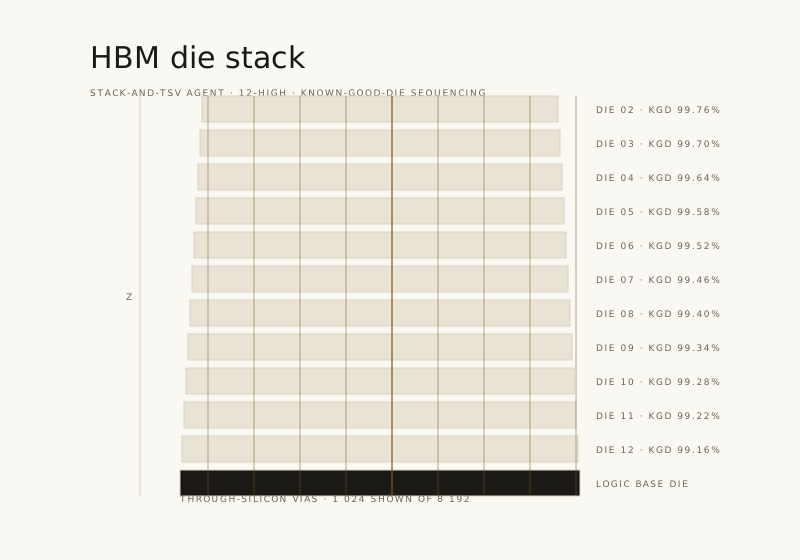
HBM and chiplet stacking optimisation
The failure mode
Good die spent on a stack that was never going to work
In a twelve-high stack, sequencing decides yield. Place a strong die onto a compromised stack and both are lost; order the stack badly and known-good-die loss compounds through the build. Approach: known-good-die sequencing and TSV and underfill planning solved as a real optimisation problem, using perception data from inspection and validated in the twin before placement. Metric: known-good-die loss per stack and composite stack yield, against a shadow-mode baseline. Status: design-partner programme [ASPIRATIONAL].
Wedge 04
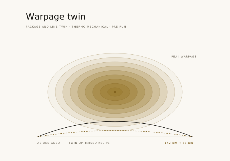
Molding, underfill and warpage control
The failure mode
Warpage that scales with the panel
Molding and underfill introduce voids and residual warpage that scale with panel area and drift with material lot and cure profile — and reveal themselves after the package is complete. Approach: warpage prediction from lot, panel history and thermal profile, with flow, pressure and cure controlled in-loop and every recipe change pre-validated in the package-and-line twin. Metric: panel scrap rate and composite yield, plus first-pass spec hit rate on new recipes. Status: design-partner programme [ASPIRATIONAL].
Method
How every one of these is measured
The same protocol, whichever wedge you choose.
-
Define the metric first
Before installation, we agree the metric, its target, the measurement method and who owns the measurement. It goes in the pilot agreement, not in a slide.
-
Establish a real baseline
Shadow mode runs for a defined period with no write-back, producing a measured baseline of the metric under your current practice — including the variance.
-
Compare like for like
Assist-mode performance is measured against the engineer plus the existing inspection or control baseline on the same packages, not against a favourable subset.
-
Publish the result internally
Whatever the outcome, it is written up with the audit trail attached. A pilot that misses its metric is documented as such.
Yield engineering managerAdvanced packaging, high-volumeShow me the shadow-mode variance before you show me the improvement. That is the number that tells me whether you understand my line.
Composite drawn from design-partner and industry conversations. Illustrative, not a customer endorsement.
Design targets
What we are aiming at
- Accuracy Defect classification at or above the engineer plus X-ray, SAM and AOI baseline on the wedge workflow.
- Yield Measurable yield improvement and scrap reduction on the target package family.
- Ramp Meaningful reduction in weeks from first silicon to target yield on a new package design.
- KGD Reduction in known-good-die loss — the most expensive material on the line.
These are the categories of metric a pilot is judged on [ASPIRATIONAL]. Specific targets are set per engagement against your measured baseline; we do not publish generic percentage claims.
Design partners
What we are looking for, and what you get
What we ask
One wedge workflow on a package family that matters, SECS-GEM or API access to the relevant tools, a named process or yield engineer to own the pilot, and permission to measure honestly.
- A defined shadow-mode period
- Engineer time for review and correction
- A signed success metric
What you get
Early access to the platform at design-partner commercial terms, direct influence over the connector library and the review console, and an engineering team that treats your line as the specification.
- Preferential commercial terms
- Roadmap influence on your tool stack
- Flagship case study, if you want it
Evidence questions
Fair challenges
-
Because someone has to be first, and being first in a category like this is where the commercial and technical leverage is. The honest counter-argument is that you should wait — and for many organisations that is the right call. We would rather you make it with clear information.
-
Only with your written permission, in the form you approve. Some design partners want the flagship case study; others want their line to remain entirely invisible. Both are fine.
-
Long enough to produce a defensible baseline and a defensible comparison — typically one to two quarters depending on volume and the variance of the metric. Shorter pilots produce numbers nobody believes.
-
Every advanced-packaging line is unusual; that is the nature of the craft. It is why we start with shadow mode on your packages rather than a demo on ours.
Design partners
Be one of the first four.
We are recruiting a small number of design partners across OSATs, IDMs and foundries, each with one measurable wedge workflow. Preferential terms, direct roadmap influence, honest measurement.